

A technical comparison for air-cooled heat exchangers and industrial heat transfer equipment.
Finned tubes improve heat transfer by increasing the surface area available on the gas or air side of a heat exchanger. Yet the method used to attach a fin to its base tube can be just as important as the fin’s dimensions. For engineers comparing wrap-on finned tubes with embedded (G-type) finned tubes, the key considerations include operating temperature, thermal cycling, tube-wall requirements, corrosion exposure, fin retention and total project cost.
L-footed, LL-footed and KL-type fins use variations of a mechanically wrapped fin strip. G-type fins use a groove in the base tube to retain the fin root. Neither construction is automatically the best choice for every project: correct selection depends on the intended duty and verified manufacturing specifications.
What Are Wrap-On Finned Tubes?
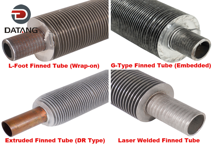
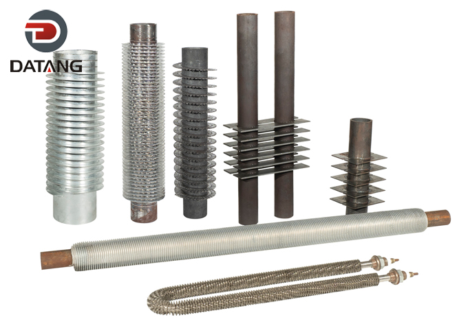
Wrap-on finned tubes are manufactured by helically winding a formed metal fin strip around the outside of a base tube under controlled tension. The design of the fin foot determines how it contacts the tube and how much of the tube surface it covers. Three widely used types are L, LL and KL.
L-Type (L-Footed) Finned Tubes
An L-shaped foot is formed at the base of the fin strip and wound tightly against the tube surface. This construction provides extended external heat transfer area, offers partial coverage of the base tube and can be cost-effective in applications with suitable temperatures and relatively moderate thermal cycling.
LL-Type (Overlapped L-Footed) Finned Tubes
LL-type fins use overlapping L-shaped feet to cover more of the exposed base tube surface. The increased coverage can be useful when environmental exposure is a selection consideration, although it should not be treated as a substitute for an appropriate corrosion assessment or protective coating.
KL-Type (Knurled L-Footed) Finned Tubes
For KL-type tubes, the tube surface is knurled and the fin foot is pressed into the prepared surface during winding. This improves mechanical grip compared with basic tension winding. Its suitability for a given temperature or cycling duty still depends on the tube and fin materials, geometry and manufacturing quality.
What Are Embedded (G-Type) Finned Tubes?
Embedded finned tubes, also called G-type or grooved finned tubes, secure the fin root in a helical groove formed in the outside of the base tube. The strip is guided into the groove, and the groove edges are mechanically displaced or backfilled to lock the fin into place. This construction is valued where a mechanically retained fin bond and resistance to thermal cycling are important.
The groove may be formed by different production methods, and its dimensions must match the selected tube, fin material and tooling. The original draft cited a groove depth of 0.25–0.30 mm; this should be treated as a configuration-specific example rather than a universal value. Manufacturers report different groove depths and forming methods.
Because the groove changes the surface profile of the pressure-containing base tube, designers must verify the effective remaining wall thickness, applicable tolerances, tube specification and project requirements. Fin-root engagement and retention should be checked during manufacture.
Wrap-On vs. Embedded Finned Tubes: Comparison Table
| Selection factor | Wrap-on: L / LL / KL | Embedded: G-type |
| Fin attachment | Tension-wound formed foot; KL adds knurled mechanical grip | Fin root retained in a formed or machined groove |
| Tube surface coverage | L: partial; LL: greater overlap; KL: depends on design | Groove secures fin; no continuous protective sleeve |
| Thermal cycling | Assess grip and contact stability for specific duty | Often selected when stronger mechanical fin retention is desired |
| Base-tube wall | No continuous helical fin-root groove in typical L/LL/KL processing | Groove profile and remaining wall thickness require verification |
| Manufacturing considerations | Winding tension, pitch, fin-foot fit and end fastening | Groove geometry, fin insertion, backfilling and retention |
| Cost | Often simpler and economical for suitable applications | Additional groove-forming operation may increase cost |
| Typical applications | Air coolers, HVAC equipment and process heat exchangers | Air-cooled heat exchangers and process duties involving thermal cycling |
Important: The table is a selection framework, not a specification or performance guarantee. Maximum allowable tube-wall temperature, pressure, vibration resistance and service life must be confirmed for the actual materials and equipment design.
How to Choose Between L, LL, KL and G-Type Finned Tubes
1. Establish the Actual Tube-Metal Temperature
Do not select a fin solely from flue-gas or ambient temperature. Confirm the expected base-tube and fin temperatures at normal operation, start-up, shutdown and potential excursions. Published maximum temperatures vary by supplier, construction and fin material. The project-specific qualified rating should control the decision.
2. Consider Thermal Cycling and Vibration
Repeated heating and cooling can affect mechanical fin contact. Where frequent cycling or significant vibration is expected, consider whether KL-type grip or G-type mechanical locking provides an appropriate margin. Excessive vibration must also be addressed at the heat exchanger design level, including tube support and airflow conditions.
3. Evaluate Corrosion and Environmental Exposure
LL-type fins provide more base-tube surface coverage than simple L-footed designs, but overlap does not create a guaranteed corrosion barrier. Evaluate condensation, chlorides, atmospheric exposure, galvanic compatibility and cleaning chemicals. Where full external protection is essential, compare extruded bimetallic fin designs and suitable coatings as alternative options.
4. Verify Fin Geometry and Air-Side Pressure Drop
Fin height, thickness and pitch influence heat transfer area, airflow resistance and fouling risk. A finer pitch increases nominal area but can make cleaning more difficult in dusty service. The best geometry should be determined from thermal and hydraulic calculations rather than maximizing fin density alone.
5. Check Tube Wall Thickness and Pressure Design
For G-type fins in particular, the groove forming process must be compatible with the base-tube wall thickness and required minimum remaining wall. The pressure design and applicable equipment code remain separate requirements from the fin attachment method. A fin type does not, by itself, establish the tube assembly’s allowable design pressure.
6. Assess Maintenance and Total Cost
Compare material and manufacturing price alongside likely inspection needs, access for cleaning, expected thermal cycling, downtime risks and replacement cost. A lower initial price can be appropriate for straightforward service, while a more mechanically secure construction may be worth evaluating for a more demanding duty.
Practical Selection Scenarios
| Project condition | Starting point for evaluation | Why |
| Moderate-temperature air cooler with limited cycling | L or LL | Economical winding; LL offers greater tube-surface coverage |
| Outdoor air cooler with exposure concerns | LL or alternative protected design | Review moisture exposure and corrosion-protection strategy |
| Duty requiring stronger fin-foot grip | KL | Knurling can improve mechanical contact |
| Frequent thermal cycling or high retention demand | G-type | Fin root mechanically locked into tube groove |
| Service outside the qualified range of mechanically attached fins | HFW or laser-welded alternatives | Assess welded construction, materials and design conditions |
These are preliminary screening suggestions. Selection must be based on the complete equipment specification and engineering review.
Where Are These Finned Tubes Used?
Wrap-on and G-type finned tubes can be used in air-cooled heat exchangers, refinery and petrochemical coolers, power-generation auxiliary systems, process heaters and other heat transfer equipment. The right construction depends more on actual duty conditions than on the industry name alone.
What Should Be Checked During Manufacturing and Inspection?
- Base tube material, outside diameter, wall thickness and traceability
- Fin strip grade, thickness, height and pitch
- Fin-foot contact for L/LL/KL or groove dimensions and engagement for G-type
- Tube straightness, fin spacing and dimensional consistency
- End securing, handling protection and visible surface condition
- Project-required testing and documentation, agreed before production
If a project requires hydrostatic, nondestructive or other specialized tests, specify their scope and acceptance criteria in the purchase documentation. Such tests should not be assumed to apply automatically to every finned tube order.
Frequently Asked Questions
Is a G-type finned tube always more efficient than an L-type finned tube?
No. G-type fins provide a different mechanical connection, but overall heat exchanger performance also depends on the fin geometry, materials, airflow, fouling conditions and operating temperatures. Compare the complete design rather than attachment style alone.
Which is better: LL-type or KL-type finned tubes?
LL-type is often considered where wider base-tube coverage is helpful. KL-type emphasizes fin-foot mechanical grip through knurling. The preferred option depends on the corrosion environment, temperature cycles, specifications and commercial priorities.
What is the difference between G-type and extruded finned tubes?
G-type fins embed a separate fin strip into a groove in the base tube. In common bimetallic extruded designs, fins are formed from an outer metal sleeve around an inner tube. The two designs have different surface coverage, manufacturing methods and temperature limitations; neither should be substituted without engineering review.
Can G-type finned tubes be used at high temperatures?
Some manufacturers publish high temperature capabilities for specific G-type configurations. However, the applicable limit depends on fin material, tube material, contact design and service conditions. Always request a manufacturer-approved maximum tube-metal temperature for the proposed construction.
What information is needed for a quotation?
Provide the fin type (or request a recommendation), base-tube material and dimensions, fin material, fin height and thickness, pitch, finished tube length, quantity, design temperatures and pressures, process fluids, corrosion or cleaning conditions, and the applicable drawings and standards.
Talk to Datang About Your Finned Tube Requirements
Cangzhou Datang Steel Pipe Co., Ltd. manufactures finned tubes for industrial heat transfer applications, including L, LL, KL and G-type constructions. If you are comparing fin attachment methods for an air cooler or process heat exchanger, share your project drawings and operating requirements for a technical review and quotation.
Website: https://datangfinpipe.com/ | Email: info@datangpipe.com