

Selecting the right fin tube is critical to the thermal performance, pressure drop, corrosion resistance, mechanical reliability, and overall cost of an air cooled heat exchanger.
Fin tube selection is not simply about choosing the highest heat-transfer coefficient. It requires balancing:
- Heat transfer requirements
- Process and ambient conditions
- Tube and fin materials
- Fin geometry
- Air-side pressure drop
- Fouling and corrosion
- Manufacturing method
- Maintenance requirements
- Cost and service life
The right fin tube configuration depends on the complete operating environment, not on a single parameter. This guide explains the key factors engineers and purchasers should evaluate when selecting fin tubes for air cooled heat exchangers.
What Is a Fin Tube in an Air Cooled Heat Exchanger?
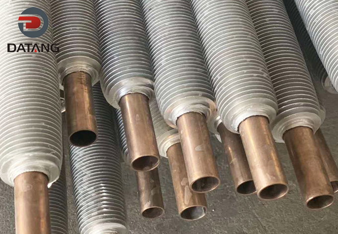
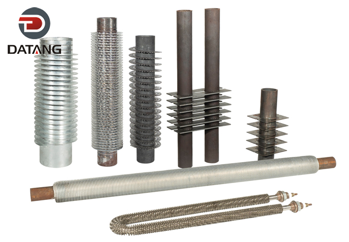
A fin tube consists of a heat-transfer tube fitted with external fins. It is widely used in air cooled heat exchangers, air coolers, radiators, condensers, and other equipment where air is used as the cooling medium.
Why Are Fins Used?
In many air cooled heat exchangers, the air-side heat transfer coefficient is considerably lower than the heat transfer coefficient on the process-fluid side. A bare tube therefore provides relatively limited heat-transfer surface to the air.
A fin increases the external surface area substantially:
Bare tube → Limited air-side surface area
Finned tube → Much larger air-side heat transfer area
By adding fins, manufacturers can achieve the required heat-transfer duty with a more practical heat exchanger size.
The goal, however, is not simply to maximize surface area. Fin geometry, fin efficiency, airflow resistance, fouling, and operating conditions must also be considered.
Basic Components of a Fin Tube
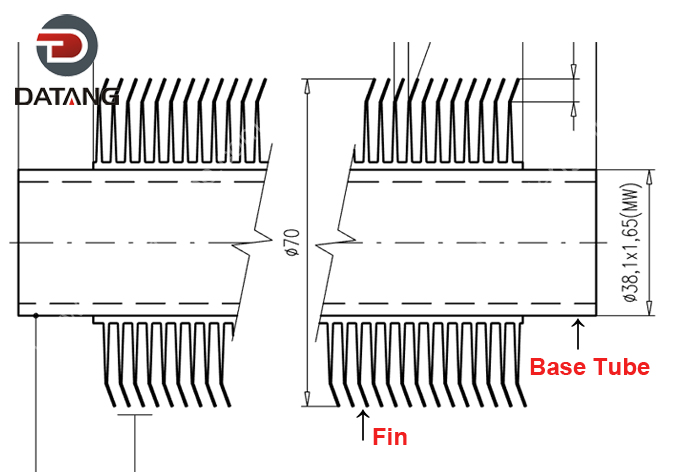
The main parameters of a fin tube include:
- Tube — carries the process fluid.
- Fin — increases the external heat-transfer area.
- Fin root — the portion of the fin connected to the tube.
- Fin tip — the outermost edge of the fin.
- Fin height — the radial distance from the tube surface to the fin tip.
- Fin thickness — the thickness of the fin material.
- Fin pitch / fin spacing — the distance between adjacent fins.
- Tube outside diameter — an important parameter for thermal, hydraulic, and mechanical design.
A Fin Tube Anatomy diagram is useful here to show these dimensions visually.
Why Fin Tube Selection Matters in Air Cooled Heat Exchangers
The fin tube is one of the most important components determining air cooler performance.
An inappropriate configuration can result in:
- Insufficient heat-transfer capacity
- Excessive air-side pressure drop
- Higher fan power consumption
- Accelerated fouling
- Difficult cleaning
- Fin corrosion
- Poor fin-to-tube thermal contact
- Reduced equipment service life
- Higher lifecycle cost
For this reason, a fin tube should be selected as part of the complete thermal and mechanical design rather than treated as an isolated component.
What Factors Should Be Considered When Selecting Fin Tubes?
1. Heat Transfer Duty
The first consideration is the required heat-transfer duty.
Important design information includes:
- Required heat duty
- Process-fluid flow rate
- Process-fluid inlet temperature
- Process-fluid outlet temperature
- Air inlet temperature
- Air outlet temperature
- Required heat-transfer area
- Overall heat-transfer coefficient
- Mean temperature difference
A simplified heat-transfer relationship is:
Q = U × A × ΔTₘ
Where:
- Q = heat duty
- U = overall heat-transfer coefficient
- A = heat-transfer area
- ΔTₘ = mean temperature difference
The required heat-transfer duty determines how much effective surface area the fin tube must provide.
However, the actual design should also consider fin efficiency and the thermal resistance between the tube, fin, process fluid, and air.
2. Process and Ambient Temperature
Temperature affects both material selection and fin geometry.
High operating temperatures may place greater demands on:
- Tube material
- Fin material
- Fin attachment method
- Thermal expansion
- Mechanical strength
- Corrosion resistance
Ambient temperature is particularly important for air cooled equipment because the available temperature difference between the process fluid and cooling air directly affects the required heat-transfer area.
For example, in hot climates, the difference between process-fluid temperature and ambient air temperature may be relatively small. The exchanger may therefore require a larger effective surface area or an optimized fin configuration to achieve the required duty.
3. Tube Material
Common tube materials include:
- Carbon steel
- Stainless steel
- Copper alloys
- Aluminum alloys
- Nickel alloys
Each material has different characteristics in terms of strength, thermal conductivity, corrosion resistance, temperature capability, availability, and cost.
| Tube Material | Typical Advantages | Typical Applications |
|---|---|---|
| Carbon steel | Low cost, good strength | General industrial service |
| Stainless steel | Good corrosion resistance | Chemical and process applications |
| Aluminum alloys | Lightweight, good thermal conductivity | Selected air-cooling applications |
| Copper alloys | High thermal conductivity | Specific cooling applications |
| Nickel alloys | Excellent corrosion resistance | Severe or highly corrosive environments |
There is no universally “best” tube material. Selection depends on the process fluid, temperature, pressure, corrosion environment, mechanical requirements, applicable standards, and project budget.
4. Fin Material
The fin material should be selected according to thermal performance, corrosion resistance, operating temperature, mechanical requirements, and manufacturing method.
Fin Material Comparison Table
| Material | Key Advantage | Typical Application |
| Carbon Steel | High strength, low cost | General industrial cooling |
| Stainless Steel | Superior corrosion resistance | Chemical & petrochemical processing |
| Copper Alloys | High thermal conductivity | Fresh water/HVAC heat exchangers |
| Aluminum Alloys | Lightweight, highly conductive | Cryogenic & specialized applications |
| Nickel Alloys | Exceptional corrosion resistance | Severe acidic/sour gas environments |
Aluminum Fins
Aluminum is widely used for air cooler fins because of its:
- High thermal conductivity
- Low weight
- Good heat-transfer performance
- Good manufacturability
Aluminum fins can be particularly attractive when weight and air-side heat-transfer performance are important.
Carbon Steel Fins
Carbon steel fins can offer:
- Good mechanical strength
- Economical material cost
- Compatibility with certain industrial applications
- Good structural durability
They may be appropriate where the operating environment and required thermal performance justify their use.
Stainless Steel Fins
Stainless steel fins may be selected when:
- Corrosion resistance is important
- The operating temperature is relatively high
- Mechanical durability is a priority
- The environment is unsuitable for conventional aluminum fins
Can Tube and Fin Materials Be Different?
Yes. The tube material and fin material do not necessarily have to be the same.
For example, a carbon steel tube combined with aluminum fins may provide a practical balance between tube strength, fin thermal conductivity, weight, and cost, depending on the application.
However, dissimilar materials require careful consideration of:
- Thermal expansion
- Fin-to-tube attachment
- Corrosion
- Galvanic effects
- Operating temperature
- Long-term mechanical integrity
Material selection should therefore be evaluated as a complete tube-fin system.
How to Select Fin Geometry
Fin geometry has a major influence on both heat-transfer performance and air-side pressure drop.
The main parameters include fin height, thickness, pitch, and overall fin configuration.
Fin Height
Increasing fin height generally increases the external heat-transfer area.
However, a higher fin is not automatically better.
Potential advantages include:
- Greater surface area
- Higher potential heat-transfer capacity
- More compact heat-transfer equipment
Potential disadvantages include:
- Higher air-side resistance
- Reduced fin efficiency
- Greater material consumption
- More difficult cleaning
- Potentially higher manufacturing cost
As fin height increases, the temperature difference between the fin root and fin tip can become more significant. Consequently, the additional surface area may contribute progressively less to useful heat transfer.
Therefore, fin height should be optimized rather than maximized.
Fin Thickness
Fin thickness should be selected by considering:
- Thermal conductivity
- Mechanical strength
- Corrosion resistance
- Manufacturing process
- Operating temperature
- Cost
A thinner fin may reduce material consumption and weight, but it must still maintain sufficient mechanical integrity and reliable attachment.
Fin Pitch / Fin Spacing
Fin pitch is one of the most important parameters in fin tube selection.
Smaller fin spacing can provide:
- More surface area per unit tube length
- More compact heat exchangers
- Potentially higher heat-transfer capacity
But it can also result in:
- Higher air-side pressure drop
- Greater fouling risk
- More difficult cleaning
- Higher fan power requirements
Larger fin spacing generally provides:
- Lower air-side pressure drop
- Better tolerance to dust and fouling
- Easier cleaning
- Better airflow passages
But it reduces the available external surface area per unit tube length.
A practical selection approach is:
Clean air + limited installation space → tighter fin spacing may be considered.
Dusty or dirty air + frequent fouling → wider fin spacing is generally more practical.
These are general guidelines only. The final fin pitch should be confirmed through thermal and hydraulic calculations.
Air-Side Pressure Drop
More fins create higher resistance to airflow, which increases fan power consumption. The objective is not maximum heat transfer, but optimum heat transfer at an acceptable pressure drop.
Fouling and Corrosion Risks
Extensive atmospheric particulate or marine salt spray requires choosing smooth fin geometries, larger pitch, and protective coatings or corrosion-resistant materials to ensure long-term performance.
How to Choose the Right Fin Tube Type
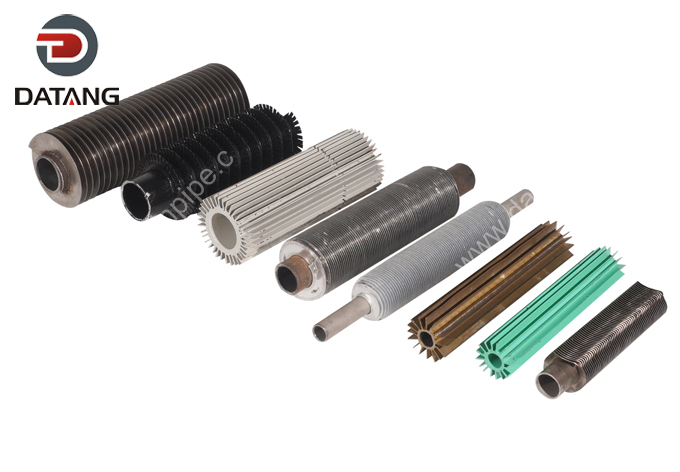
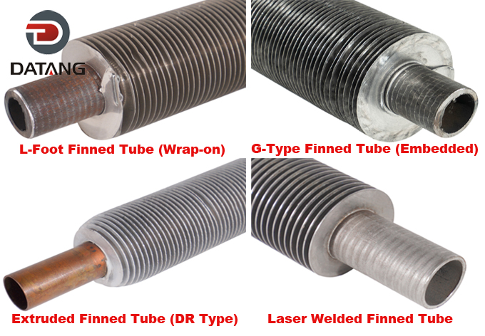
Different fin tube manufacturing methods provide different combinations of thermal performance, mechanical attachment, corrosion resistance, temperature capability, and cost.
1. Embedded Fin Tubes (G-Type)
Fins are mechanically embedded into a machined groove on the outer wall of the base tube.
-
Operating Temp: Up to 400C°.
-
Advantages: High mechanical bond strength, excellent thermal contact, resilient against vibration.
2. Extruded / Bimetallic Fin Tubes
An outer aluminum muff tube is cold-extruded over an inner base tube, forming high integrally rolled fins.
-
Operating Temp: Up to 300C°.
-
Advantages: 100% mechanical contact, complete outer corrosion protection for the base tube, easy high-pressure washdowns.
3. Tension Wrapped Fin Tubes (L, LL, KL-Type)
Fin strip is wrapped under tension around the tube outer surface.
-
L-Type: L-shaped root covers outer tube partially.
-
LL-Type: Overlapping L-roots cover base tube completely.
-
KL-Type: Knurled foot provides enhanced grip into the base tube wall.
-
Operating Temp: 130C° to 250C° depending on subtype.
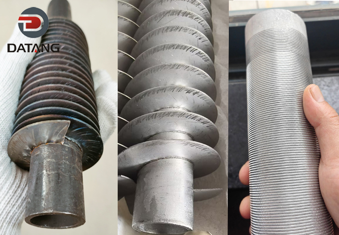
4. Welded Fin Tubes (High-Frequency & Laser Welded)
Fins are continuously welded to the base tube.
-
Operating Temp: Up to 500C°+.
-
Advantages: Ideal for severe thermal cycles, high temperatures, and heavy-duty soot or ash environments.
The appropriate choice depends on the application, material requirements, operating conditions, and manufacturing capabilities.
Fin Tube Type Comparison
| Fin Tube Type | Thermal Contact | Mechanical Integrity | Temperature Capability | Typical Considerations |
| Embedded fin tube | Good | Good | Application-dependent | Economical and widely used |
| Extruded/bimetallic | Excellent | Excellent | Application-dependent | High performance and corrosion considerations |
| Welded fin tube | Good to excellent | Very good | Suitable for demanding service | Heavy-duty applications |
| Integral fin tube | Excellent | Excellent | Material-dependent | High-integrity applications |
The final selection should be based on actual design conditions rather than the manufacturing method alone.
How Operating Conditions Affect Fin Tube Selection
A fin tube that performs well in one environment may not be suitable for another.
Process Temperature
As process temperature increases, engineers should evaluate:
- Tube material strength
- Fin material temperature capability
- Thermal expansion
- Fin attachment integrity
- Corrosion behavior
- Long-term mechanical reliability
Ambient Temperature
Ambient temperature directly influences the available temperature driving force.
In hot environments, the cooling air may be much closer in temperature to the process fluid. This can increase the required heat-transfer surface or influence the selection of fin geometry and airflow.
Air Quality
Cooling air may contain:
- Dust
- Sand
- Salt
- Humidity
- Industrial pollutants
- Chemical contaminants
In these conditions, maximum heat-transfer area should not be the only design objective.
The engineer should balance:
Heat transfer + fouling resistance + corrosion resistance + cleanability
This is especially important for outdoor air cooled heat exchangers.
How Fouling and Corrosion Affect Fin Tube Selection
Real-world performance can deteriorate significantly when fouling or corrosion is overlooked during fin tube selection.
Fouling
Dust and other contaminants can accumulate on fin surfaces and restrict airflow.
Fouling may affect:
- Airflow
- Air-side heat transfer
- Pressure drop
- Fan power
- Cleaning frequency
- Long-term heat exchanger capacity
A high-density fin configuration that performs well under clean conditions may become difficult to maintain in a heavily contaminated environment.
For dusty service, wider fin spacing and easier access for cleaning may provide a better lifecycle solution.
Corrosion
Corrosion risks can come from:
- Atmospheric exposure
- Salt spray
- Humidity
- Process-fluid leakage
- Chemical exposure
- Industrial pollutants
Material selection should therefore consider both the tube-side and air-side environments.
Galvanic Corrosion
Special attention may be required when dissimilar metals are used together.
For example, an aluminum fin combined with a carbon steel tube can require careful evaluation of galvanic corrosion, moisture exposure, coating, interface design, and the specific operating environment.
This is one reason why selecting materials based solely on thermal conductivity can lead to poor long-term results.
How Fin Efficiency Affects Fin Tube Selection
A common misconception is that every square centimeter of fin surface contributes equally to heat transfer.
Not all fin surface area contributes equally to heat transfer.
The fin root is generally at a higher temperature because it is closer to the tube. As heat travels toward the fin tip, the temperature difference between the fin and surrounding air changes.
As a result, fin efficiency is normally less than 100%.
Important concepts include:
- Fin efficiency
- Fin effectiveness
- Overall surface efficiency
This explains why increasing fin height indefinitely does not necessarily produce a proportional increase in heat-transfer performance.
A well-designed fin tube therefore seeks an appropriate balance between:
Surface area + fin efficiency + airflow + pressure drop + manufacturing cost
rather than simply maximizing fin dimensions.
How Air-Side Pressure Drop Affects Fin Tube Selection
Heat-transfer performance is only one side of the design.
Increasing fin density can increase the available heat-transfer area, but it may also restrict airflow.
The relationship can be summarized as:
More fins → More surface area
but potentially:
More fins → Higher air resistance → Higher fan power
This means the design target should not simply be:
Maximum heat transfer
A more realistic engineering objective is:
Optimum heat transfer with acceptable air-side pressure drop and fan power.
The selection may therefore need to consider:
- Air velocity
- Airflow rate
- Air-side pressure drop
- Fan capacity
- Fan efficiency
- Energy consumption
- Available installation space
A configuration with slightly lower theoretical heat-transfer performance may provide a better overall solution if it significantly reduces fan power and maintenance requirements.
Fin Tube Selection by Application
Petrochemical Industry
Petrochemical air cooled heat exchangers may operate under demanding conditions involving elevated temperatures, corrosive fluids, outdoor exposure, and continuous operation.
Important selection considerations include:
- Temperature capability
- Corrosion resistance
- Mechanical reliability
- Fin attachment
- Long service life
- Applicable industry standards
Power Plants
Power-generation applications can involve large heat duties and continuous operation.
Key considerations include:
- Large heat-transfer capacity
- Ambient temperature
- Airflow requirements
- Fan power
- Equipment reliability
- Maintenance requirements
Natural Gas Processing
Natural gas processing applications require careful consideration of the gas composition and operating conditions.
Depending on the process, engineers may need to evaluate:
- Corrosion
- Operating temperature
- Low-temperature conditions
- Fouling
- Material compatibility
- Pressure and mechanical requirements
HVAC and Refrigeration
HVAC and refrigeration systems often place greater emphasis on:
- Compact size
- Aluminum fins
- High heat-transfer performance
- Low air-side pressure drop
- Weight
- Cost
The preferred fin tube configuration may therefore differ significantly from that used in a heavy-duty petrochemical air cooler.
Dusty Industrial Environments
For dusty environments, maximizing fin density may not be the best strategy.
More practical considerations can include:
- Wider fin spacing
- Lower fouling sensitivity
- Easy cleaning
- Accessible fin surfaces
- Adequate airflow passages
- Corrosion resistance
In these applications, maintainability can be just as important as initial thermal performance.
Common Fin Tube Selection Mistakes
Mistake 1: Choosing Fins Based Only on Heat-Transfer Area
A larger surface area does not automatically mean better overall performance.
Fin efficiency, airflow, pressure drop, fouling, and operating conditions also affect actual performance.
Mistake 2: Ignoring Air-Side Pressure Drop
A highly dense fin configuration may increase heat-transfer area but also increase airflow resistance.
This can result in:
- Oversized fans
- Higher fan power
- Increased operating costs
- Reduced system efficiency
Mistake 3: Selecting Materials Based Only on Thermal Conductivity
High thermal conductivity is valuable, but it is not the only material-selection criterion.
Engineers should also evaluate:
- Corrosion resistance
- Operating temperature
- Mechanical strength
- Thermal expansion
- Compatibility
- Cost
- Service life
Mistake 4: Ignoring Fouling
A fin tube designed for clean air may not perform as expected in a dusty industrial environment.
Fouling should be considered during the initial design rather than treated as a maintenance issue after installation.
Mistake 5: Ignoring Fin-to-Tube Contact
The thermal interface between the fin and tube is critical.
Poor contact can increase thermal resistance and reduce the practical benefit of the fin surface.
The attachment method should therefore be evaluated together with the expected operating temperature, thermal expansion, mechanical loading, and corrosion environment.
Mistake 6: Selecting a Standard Fin Tube Without Thermal Calculation
Standard dimensions can be useful starting points, but the final configuration should be determined by actual operating conditions.
A proper design should consider thermal performance, airflow, pressure drop, materials, fouling, corrosion, mechanical requirements, and manufacturing feasibility.
Fin Tube Selection Checklist
Before purchasing or specifying fin tubes for an air cooled heat exchanger, prepare the following information:
-
[ ] Required heat duty
-
[ ] Process fluid
-
[ ] Process flow rate
-
[ ] Process inlet temperature
-
[ ] Process outlet temperature
-
[ ] Operating pressure
-
[ ] Ambient temperature
-
[ ] Required airflow
-
[ ] Required heat-transfer area
-
[ ] Tube material
-
[ ] Fin material
-
[ ] Tube outside diameter
-
[ ] Fin height
-
[ ] Fin thickness
-
[ ] Fin pitch / spacing
-
[ ] Fouling conditions
-
[ ] Corrosion environment
-
[ ] Cleaning requirements
-
[ ] Fan limitations
-
[ ] Design life
-
[ ] Applicable standards
-
[ ] Manufacturing and installation requirements
Having this information available makes it much easier for a fin tube manufacturer or heat exchanger engineer to recommend a suitable configuration.
Frequently Asked Questions
What is the best fin tube for an air cooled heat exchanger?
There is no single best fin tube for every air cooled heat exchanger. The appropriate choice depends on heat duty, process and ambient temperatures, tube and fin materials, fin geometry, air-side pressure drop, fouling, corrosion, operating temperature, and required service life.
How do I choose fin spacing?
Fin spacing should balance heat-transfer area, air-side pressure drop, fouling risk, and cleaning requirements. Tight fin spacing can provide more surface area, while wider spacing is generally more suitable for dusty or heavily fouling environments. Final selection should be confirmed through thermal and hydraulic calculations.
What material is commonly used for air cooler fins?
Aluminum is widely used because it combines relatively high thermal conductivity, low weight, and good manufacturability. However, carbon steel, stainless steel, and other materials may be appropriate depending on temperature, corrosion, mechanical, and cost requirements.
What is the difference between embedded and extruded fin tubes?
Embedded fin tubes use a mechanical attachment method to connect the fin to the tube, while extruded or bimetallic fin tubes typically provide an integrated fin structure around an inner tube. Bimetallic designs can offer excellent fin-to-tube contact and may provide advantages in demanding thermal and corrosion environments.
Does higher fin density always improve heat transfer?
No. Higher fin density increases surface area, but it can also increase air-side pressure drop, fouling risk, and fan power consumption. In addition, not all additional fin area contributes equally because fin efficiency decreases as temperature gradients within the fin increase.
How does fin height affect heat exchanger performance?
Increasing fin height generally increases surface area, but the improvement is not necessarily proportional. Higher fins can also increase airflow resistance and reduce fin efficiency. Fin height should therefore be optimized based on thermal and hydraulic calculations.
How do fouling conditions affect fin tube selection?
Fouling can reduce airflow and heat-transfer performance while increasing pressure drop and maintenance requirements. For dusty environments, wider fin spacing and easier cleaning may be preferable to a high-density fin configuration.
How do I calculate the required fin tube area?
A simplified heat-transfer relationship is Q = U × A × ΔTₘ. However, finned surfaces require consideration of fin efficiency, surface efficiency, air-side and tube-side heat-transfer coefficients, fouling resistance, and pressure drop. A complete thermal design calculation is therefore recommended rather than relying on the basic equation alone.
Conclusion
Selecting fin tubes for an air cooled heat exchanger is a multi-parameter engineering decision.
The objective is not simply to maximize heat-transfer area or choose the material with the highest thermal conductivity. A successful fin tube configuration must balance thermal performance, air-side pressure drop, material compatibility, corrosion resistance, fouling, mechanical reliability, manufacturability, maintenance, and lifecycle cost.
The key parameters to evaluate include:
- Heat duty
- Process and ambient temperatures
- Tube and fin materials
- Fin height and thickness
- Fin pitch
- Fin attachment method
- Air-side pressure drop
- Fouling and corrosion
- Cleaning requirements
- Fan limitations
- Design life
The best fin tube is therefore the one that provides the required thermal performance while remaining reliable, maintainable, and economically practical throughout the equipment’s operating life.
If you are unsure which fin tube configuration is suitable for your air cooled heat exchanger, provide your operating conditions and required heat duty. An experienced fin tube manufacturer or heat exchanger engineering team can evaluate the thermal, hydraulic, material, and mechanical requirements and recommend an appropriate tube and fin configuration.
Need Help Selecting the Right Fin Tube?
Choosing the right fin tube for an air cooled heat exchanger depends on more than tube size or fin density. Heat duty, operating temperature, airflow, pressure drop, materials, fouling conditions, corrosion environment, and required service life all need to be considered together.
Not sure which fin tube configuration is right for your application? Send us your operating conditions and we can help evaluate a suitable solution.
Contact us today for a technical recommendation and RFQ.