


As two leading high-efficiency heat transfer solutions offered by Datang Finned Tube, longitudinal finned tubes and helically welded finned tubes differ significantly in structure, thermal performance, and operating conditions. Choosing the optimal type depends heavily on the specific application—most notably fluid dust load, flow velocity, and heat transfer demands.
What is a Longitudinal Finned Tube?
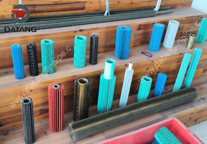
Longitudinal finned tubes are high-efficiency heat transfer components featuring fins positioned parallel to the tube axis. By expanding the surface area and directing fluid in a smooth, longitudinal flow, they maximize thermal performance—ideal for applications where fluid moves along the length of the tubing.
Longitudinal Finned Tubes Technical Specification Sheet
| Parameter | Specification / Range | Remarks |
|---|---|---|
| Base Tube O.D | 19 mm ~ 76 mm | – |
| Base Tube Thickness | 2.0 mm ~ 6.0 mm | – |
| Fin Height | 6.0 mm ~ 32.0 mm | – |
| Fin Thickness | 0.8 mm ~ 1.2 mm | – |
| Fin NO. | 4, 8, 16, 24, 32, 40, 48 (Pc) | Unit: Pieces/Tube |
| Tube Length | ≤ 15 Mtrs | Max length 15 meters |
| Base Tube Material | • Carbon Steel: A106, A333, A179, A210, P5, P11, P22 • Stainless Steel: 304, 316, Duplex, Super Duplex • Copper and Copper Alloys: Brass, Aluminum Brass, Cupronickel 70/30-90/10 • Nickel Alloys: Monel 400, Inconel 625 |
Covers various corrosion-resistant and high-temperature materials |
| Fin Material | Carbon Steel, Alloy Steel, Stainless Steel, Cupronickel | Must be matched or compatible with the base tube material |
What is a Welded Helical Finned Tube?
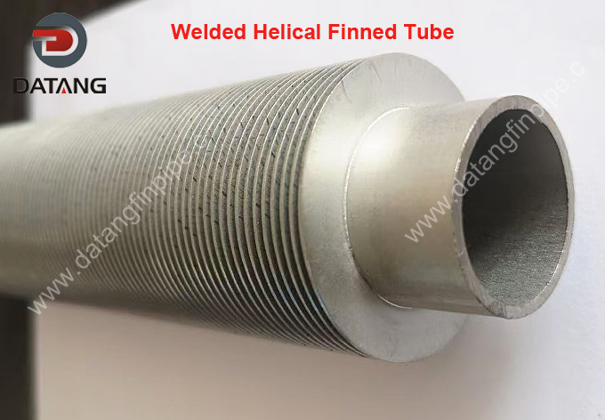
Welded helical finned tubes feature continuous spiral fins welded onto the outer surface of the base tube to boost heat transfer performance. High-frequency welding (HFW) is the most widely adopted process, alongside laser welding and brazing techniques. These components are essential in boilers, heat exchangers, and waste heat recovery systems.
Helically Welded Finned Tube Technical Specification Sheet
| Item / Parameter | Specification / Material Grade | Unit / Details |
| Base Tube Outer Diameter (O.D.) | 19.0 – 219.0 | mm |
| Base Tube Wall Thickness | 2.0 – 16.0 | mm |
| Fin Height | 8.0 – 38.0 | mm |
| Fin Thickness | 0.8 – 3.0 | mm |
| Fin Pitch / Density | 2.0 – 25.0 (60 – 500 FPM) | mm (Fins Per Meter) |
| Fin Type / Pattern | Solid (Plain) or Serrated (Cut) | Type Options |
| Welding Process | High-Frequency Resistance Welding (HFW) / Laser Welding | Process Options |
| Max Tube Length | ≤ 28.0 | Mtr |
| Base Tube Material |
Carbon Steel (A106, A179, A210, A333)
Alloy Steel (P5, P11, P22, P91)
Stainless Steel (304/304L, 316/316L, 321, 347, Duplex, Super Duplex)
Nickel Alloys (Inconel 625, Hastelloy) |
Multiple Grade Options |
| Fin Material | Carbon Steel, Stainless Steel (304/304L, 316/316L, 430), Corten Steel, Alloy Steel | Multiple Material Options |
Longitudinal vs Welded Helical Finned Tubes Structural Differences
Longitudinal Finned Tubes
-
Fin Layout: Fins are arranged parallel to the base tube axis, aligning directly with the fluid flow direction. The fin count is typically a multiple of four, resistance-welded in pairs on opposing sides of the base tube.
-
Heat Transfer Area: Expands the surface area to roughly 3–5 times that of a bare tube, providing a relatively modest extension.
-
Airway Design: Features straight, longitudinal flow channels without helical bends, ensuring wide and unobstructed passages.
Helically Welded Finned Tubes
-
Fin Layout: Fins are continuously wrapped around the outer surface of the base tube in a spiral pattern, with fin pitch flexibly adjustable between 2–10 mm based on operating conditions.
-
Heat Transfer Area: Expands the heat transfer area up to 3–12 times that of a bare tube; serrated (cut-fin) variants can further enhance heat transfer performance.
-
Welding Process: Primarily manufactured via high-frequency resistance welding (HFW) or laser welding. The steel strip and base tube surface are fused under pressure, achieving a weld fusion rate of 90%–99%.
Longitudinal vs Welded Helical Finned Tubes Dust-proof Capability
Longitudinal Finned Tubes
-
Although their heat transfer area per unit length is smaller than that of helical finned tubes, they offer exceptional resistance to ash accumulation. In high-dust flue gas environments, the straight channels are less prone to clogging; even if minor ash deposits accumulate, they are easily swept away by the airflow or dislodged by gravity, maintaining stable thermal performance over the long term. Vertical installation further aids in the gravity-driven drainage of condensate or dust removal.
Helically Welded Finned Tubes
-
In clean environments, their significantly larger surface area and boundary layer disruption effect yield heat transfer efficiency far superior to longitudinal finned tubes. However, the “pockets” formed by the helical structure serve as a breeding ground for ash deposition. Once ash builds up, it not only vastly increases flow resistance, but the ash layer itself—being an extremely poor thermal conductor—severely degrades heat transfer performance and may even lead to local tube wall overheating.
Longitudinal Finned Tubes vs Welded Helical Finned Tubes Manufacturing Process
Longitudinal Finned Tubes
-
Simple Construction: Pre-formed “U”-shaped or strip fins are welded onto the base tube using resistance welding, high-frequency welding, or similar methods.
-
Cost-Effective Production: Easy to manufacture with relatively low equipment investment costs.
Helically Welded Finned Tubes
-
High-Efficiency Process: High-frequency welding (HFW) is the primary manufacturing method, fusing the steel strip to the base tube via high-frequency current as it wraps continuously around the tube.
-
High Joint Integrity: Delivers high bond strength, minimal contact thermal resistance, and fast production rates.
-
Critical Quality Factors: Weld quality—specifically full fusion and freedom from porosity—is the primary factor determining long-term service life and performance.
Longitudinal vs Welded Spiral Finned Tubes Selection Guide
Selection Longitudinal Finned Tubes
Prioritize for high-dust and high-velocity gas environments, such as underground mine heat exchange, flue gas heat recovery in dusty metallurgical workshops, and highly abrasive industrial furnaces. This choice trades a degree of heat transfer efficiency for superior operational adaptability.
-
High Dust Content & Sticky Particulates: Ideal for challenging fluids, such as cement kiln tail gas or metallurgical dust.
-
Strict Pressure Drop Limits: Best when system pressure drop is highly sensitive and fan power is restricted.
-
Linear Parallel Flow: Required when fluid outside the tubes must flow in a single, straight direction (e.g., double-pipe heat exchangers).
-
Vertical Equipment Setup: Necessary when vertical installation is required to utilize gravity for condensate drainage or dust removal.
Selection Helically Welded Finned Tubes
Widely applied in clean, low-to-medium temperature, and low-to-moderate dust environments—such as boiler economizers, air preheaters, petrochemical waste heat recovery systems, and grain drying exchangers—striking a balance between maximum heat transfer efficiency and cost control.
-
Clean or Low-Dust Fluids: Suitable for clean air, natural gas flue gas, or steam.
-
Maximum Heat Transfer Efficiency: Primary goal is to maximize heat flux and transfer more thermal energy within a compact footprint.
-
Sufficient Pressure Drop Allowance: The system can accommodate higher pressure drops to achieve higher heat transfer coefficients.
-
Self-Cleaning under Light Dust: Takes advantage of helical flow turbulence to self-clean small amounts of non-sticky dust particles.
Summary
-
Longitudinal Finned Tubes: Anti-clogging & low flow resistance.
-
Helically Welded Finned Tubes: High thermal efficiency & strong turbulence generation.
In practical engineering applications—such as in the cement industry—AQC (Air Quenching Cooler) boilers at the kiln head primarily utilize helically finned tubes due to lower dust concentration and high abrasive characteristics. Conversely, SP (Suspension Preheater) boilers at the kiln tail, which face high dust loads and sticky particulates, favor longitudinal finned tubes or specially engineered anti-fouling helical finned tubes.
