


The operational stability of industrial heat exchangers relies on the precise matching of technical parameters and material properties. In industrial heat exchange systems, welded finned tubes serve as the primary heat transfer elements. In particular, High-Frequency Resistance Welded (HFW) finned tubes achieve a fusion rate of over 95% between the base tube and the fins, delivering exceptional heat transfer performance and superior mechanical vibration resistance. Consequently, they are widely utilized in refinery heaters, power plant boilers, waste heat recovery units (WHRU) heat exchangers, economizers, and air coolers.
At Datang Finned Tube, the manufacturing process of these components strictly adheres to rigorous industrial standards. This ensures that every weld joint and dimensional parameter fulfills the performance demands of B2B infrastructure projects. We mandate full traceability for raw materials to guarantee the integrity of the base tubes. The finned tube dimensions undergo strict and precise measurements, which are vital for maintaining system pressure and thermal flow efficiency. Our factory enforces a mandatory first-article inspection (FAI); mass production only commences once the initial sample passes all technical qualifications.
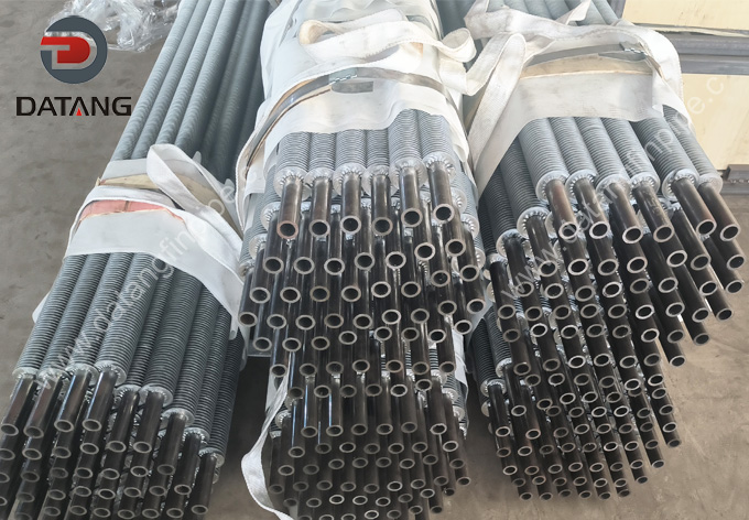
Material Classification and Advantages
When selecting the appropriate materials for welded finned tubes, it is essential to evaluate both the corrosiveness of the flue gas and the internal pressure of the process fluid. Datang Finned Tube offers a comprehensive range of steel grades to meet the stringent demands of diverse industrial environments.
Carbon Steel
Material specifications such as ASTM A179 (cold-drawn seamless carbon steel tubes commonly used in heat exchangers), ASTM A192 / A210 (high-pressure carbon steel tubes for boilers), and ASTM A106 Gr. B (widely utilized in petrochemical applications) are meticulously selected. These materials feature predictable thermal expansion properties and deliver excellent weldability for the high-frequency resistance welding (HFW) process.
Stainless Steel
Industry-standard materials complying with ASTM A312 / A240 (such as TP304, TP316L, TP321, and TP347) are engineered for highly corrosive or ultra-high-temperature environments. These steel grades effectively prevent oxidation, ensuring long-term structural integrity even under prolonged exposure to aggressive media.
High-Temperature Alloy Steel
Materials such as ASTM A213 / A335 (including T5, T9, T11, T22, and P22) are extensively used in the manufacturing of superheater components. They are chosen for their outstanding creep resistance, excellent high-temperature oxidation resistance, and superior high-pressure performance capabilities.
Dimensional Accuracy and Manufacturing Tolerances
The efficiency of a finned tube depends entirely on its geometric profile. Our production lines are highly optimized to maintain strict dimensional accuracy, ensuring that technical specifications translate directly into superior on-site performance.
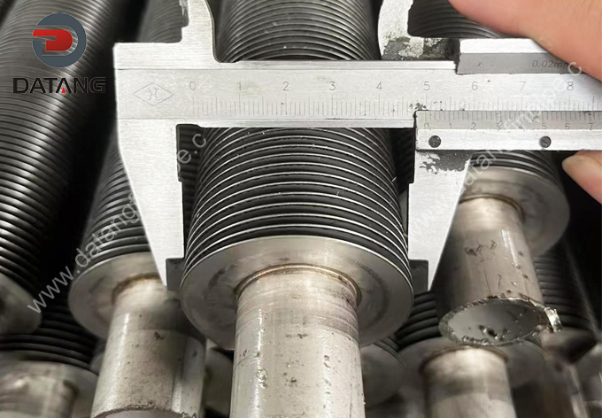
Base Tube Outer Diameter (OD)
The outer diameter ranges from 12.7 mm to 279 mm (3/8″ to 10″), with the most common sizes falling between 1″ and 2.5″ (25.4 mm to 63.5 mm). Precision control mechanisms guarantee that each tube perfectly fits its corresponding tubesheet or header interfaces.
Base Tube Wall Thickness (WT)
Wall thickness ranges from 2.0 mm to 28.6 mm (0.08″ to 1.1″). To ensure high-quality welding and structural integrity, the base tube must have sufficient thickness, typically $\ge$ 2.0 mm.
Tube Length (L)
We can manufacture finned tubes with a single-tube length of $\le$ 30,000 mm (98.4 ft). Our ability to supply 30-meter continuous finned tubes is one of our core competitive advantages. Lengths can be fully customized based on the actual spans of massive industrial boilers or air cooler tube bundles.
Fin Height (H)
Fin height ranges from 5 mm to 38 mm (0.25″ to 1.5″). This parameter determines the extended surface area and the rate of heat transfer. To optimize thermal efficiency, it is generally recommended that the fin height does not exceed the radius of the base tube.
Fin Thickness (T)
Fin thickness ranges from 0.8 mm to 3.5 mm (0.02″ to 0.14″), achieving an optimal balance between vibration resistance and thermal conductivity. Carbon steel fins typically range from 0.8 mm to 3.0 mm, while stainless steel fins range from 0.8 mm to 2.5 mm.
Fin Density / Pitch
The fin pitch ranges from 3.0 mm to 33.0 mm, corresponding to a density of 43 to 287 fins per meter (1 to 8 FPI / Fins Per Inch). Selecting the proper fin density is crucial to mitigating fluid fouling tendencies; for instance, a lower fin density is preferred in flue gas environments prone to heavy ash accumulation.
Production process
High-Frequency Resistance Welding (HFW) Process
The superior performance of our products is driven by state-of-the-art High-Frequency Resistance Welding (HFW) technology. By utilizing localized electromagnetic induction heating, this process creates a robust weld fusion between the fin and the tube wall, guaranteeing a 98% metallurgical bond.
This structural integration completely eliminates the contact thermal resistance commonly associated with traditional tension-wound (L/LL/KL-type) finned tubes. Because the heat-affected zone (HAZ) is kept exceptionally narrow, the base tube is protected from embrittlement under high-pressure conditions. Consequently, the equipment maintains highly stable thermal performance throughout its entire operational lifecycle.
Laser Welding Process
For ultra-premium performance, we also utilize advanced laser welding technology. This process employs a highly concentrated, high-energy-density laser beam to deliver localized, ultra-precise heating. It achieves full-penetration welding between the fin and the base tube, ensuring a 100% bonding rate and virtually zero contact thermal resistance.
This engineered design thoroughly overcomes the limitations of traditional high-frequency welding, such as incomplete root penetration and fin wrinkling at the base. Furthermore, the extremely minimized heat-affected zone (HAZ) effectively controls microstructural phase changes, preventing the base tube from becoming brittle under complex working conditions. As a result, this process breaks through material compatibility limits, makes subsequent tube-bending operations easier, and delivers outstanding heat transfer efficiency and anti-fouling performance over the equipment’s entire lifespan.
Customization Capabilities and Technical Verification
Datang Finned Tube acts as a strategic technical partner for your projects. Every single order undergoes a rigorous quality inspection workflow, where material dimensions are meticulously cross-verified against the relevant thermal design parameters. Furthermore, non-destructive testing (NDT) is thoroughly implemented to guarantee product quality, ensuring absolute bonding integrity between the fin and the tube, alongside flawless dimensional accuracy.
By combining advanced metallurgy with cutting-edge welding technologies, we empower our clients to build heat exchangers that maximize thermal efficiency and minimize spatial footprints—all without compromising long-term durability. For international buyers seeking manufacturing excellence, our factory delivers the ultimate combination of technical expertise and cost-effectiveness.
Custom Parameters Required for Ordering
To facilitate seamless technical communication and precision procurement, please provide the following comprehensive parameter specifications when submitting your inquiry or order:
-
Base Tube Specifications & Material Grade: Outer Diameter (OD) x Wall Thickness (WT) x Length (ASTM A179, 25 x 3 x 9000 mm)
-
Fin Dimensions & Material Grade: Fin Height (H) x Fin Thickness (T) x Fin Density/Pitch (Solid/Serrated Steel, 15 mm x 1.0 mm x 236 fins/meter or FPI)
-
Unfinned Bare Ends: The net length at both tube ends left unwelded (typically 50 to 150 mm) to allow for tubesheet insertion and on-site welding.