

What are finned tubes?
Finned tubes, also known as heat exchange tubes, are heat transfer elements used to enhance heat transfer, increasing heat transfer efficiency by increasing surface area. They are suitable for high-temperature, high-pressure, and corrosive environments in industries such as boilers, power generation, and metallurgy. Their core function is to reduce contact thermal resistance and provide corrosion and wear resistance. They are commonly used in waste heat recovery and heat exchange equipment.
Production processes include high-frequency welding and three-roll cross-rolling. High-frequency welded spiral finned tubes are widely used due to their high degree of automation. The three-roll cross-rolling method achieves seamless bonding through integral rolling.
Finned tubes are categorized by process, such as rolling or welding. Fin shape can be categorized as spiral or longitudinal. Materials include copper, aluminum, and steel, and they can be adapted to applications such as air cooling and waste heat recovery, depending on the intended use. Tube bundles can be arranged in staggered (for high heat transfer efficiency) or in-line (for low resistance). The tube box structure design must be adjusted based on fluid pressure and temperature differentials.
Fin Tube Performance Requirements
As heat exchange elements, fin tubes operate under high-temperature flue gas conditions for extended periods. For example, fin tubes used in boiler heat exchangers operate in harsh environments characterized by high temperatures, high pressures, and corrosive atmospheres. This requires fin tubes to possess high performance specifications.
1. Anti-corrosion
2. Anti-wear
3. Low contact resistance
4. High stability
5. Anti-dust accumulation
Current Status of Fin Tube Production
Fin-on-Fin
The fin-on-fin process involves pre-pressing a batch of individual fins. These fins are then manually or mechanically attached to the outer surface of the tube at a specific pitch.
This is the earliest method of manufacturing fin tubes. Due to its simplicity, low technical requirements, low cost, and easy maintenance, the fin-on-fin process is still used by many factories. This labor-intensive process is suitable for the financial and technical needs of small factories or township enterprises.
Manual finning is performed manually. Fins are pressed into place one by one using tools and manual labor. Because the fin-pressing force is limited, the interference fit is small, making the fins prone to loosening.
Mechanical finning is performed on a fin-pressing machine. Because the fins are pressed into place using mechanical impact or hydraulic pressure, the high pressure allows for a larger interference fit. The bond between the fins and the tube is strong and resists loosening. Mechanically driven finning machines offer high productivity, but are noisy, unsafe, and create poor working conditions. Hydraulically driven finning machines, while not subject to these issues, are more expensive, require more skilled operators, and offer lower productivity.
Inlaid Spiral Fins
Inlaid spiral fin tubes are pre-machined with spiral grooves of a specific width and depth in the steel tube. The steel strip is then inserted into the tube on a lathe. During the winding process, a certain preload forces the strip tightly into the grooves, ensuring a certain contact area between the strip and the tube. To prevent the steel strip from springing back and falling off, both ends of the strip must be welded to the steel pipe. To facilitate insertion, a certain amount of side clearance should be maintained between the strip and the spiral groove. If this clearance is too small, resulting in interference fit, the insertion process will be difficult.
The wrapped strip will always rebound, resulting in a poor fit between the strip and the bottom of the spiral groove. Fin insertion can be performed on general-purpose equipment at a low cost, but the process is complex and inefficient.
Brazed Spiral Fin Tubes
The brazed spiral fin tube process is a two-step process.
1. Wrap the steel strip perpendicular to the tube axis in a spiral pattern around the outer surface of the tube and weld the ends of the strip to the tube to secure it.
2. To eliminate the gap at the contact point between the strip and the tube, braze the strip and tube together.
Because this method is expensive, an alternative is often used: placing the wrapped tube in a zinc bath for full-body hot-dip galvanizing. Although the galvanizing solution may not fully penetrate the tiny gaps between the fins and the steel tube, a complete galvanized layer forms on the outer surfaces of the fins and the steel tube.
Spiral fin tubes using full hot-dip galvanizing are limited by the thickness of the galvanizing layer (a thick galvanizing layer has poor durability and is prone to detachment). Furthermore, the galvanizing solution cannot fully penetrate the gaps, so the bond between the fins and the steel tube remains low.
Zinc has a lower heat transfer coefficient than steel (approximately 78% of that of steel), resulting in lower heat transfer capacity. Zinc is highly corroded in acids, alkalis, and sulfides. Therefore, galvanized spiral fin tubes are not suitable for air preheaters (recovering waste heat from boiler flue gases).
High-frequency welded spiral fins
High-frequency welded spiral fin tubes are one of the most widely used spiral fin tubes and are widely used for waste heat recovery in the power, metallurgy, and cement industries, as well as in the petrochemical industry.
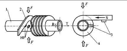
High-frequency welded spiral finned tubes are produced by wrapping a steel strip around a steel tube. The skin effect and proximity effect of high-frequency current heat the steel strip and the outer surface of the tube until they become plastic or melt. The weld is then completed under the pressure of the wrapped strip. This high-frequency welding is essentially a solid-phase welding process. Compared to methods such as inlaying, brazing (or integral hot-dip galvanizing), it offers superior product quality (with a high fin weld rate of up to 95%), productivity, and automation.
Three-roller cross-rolled integral spiral finned tubes
The production principle of three-roller cross-rolled integral spiral finned tubes is as follows:
A core rod is lined inside a plain tube. Driven by the rotating roller blades, the seamless steel tube passes through the cavity formed by the rolling groove and the core head to form fins on its outer surface. Because the base tube and outer fins are an integral unit, this method eliminates contact thermal resistance losses and offers high heat transfer efficiency. Compared to welding, the three-roll cross-rolling process offers advantages such as high production efficiency, low raw material consumption, and high heat transfer efficiency for the finned tubes produced.
Three-roll cross-rolling technology for integral spiral finned tubes has been successfully applied to single-fin or composite-fin tubes with copper or aluminum fins, as well as steel low-fin tubes. Steel integral finned tubes are most commonly low-fin tubes on the market, while integral high-fin tubes are mostly made of aluminum, copper, and other materials and are generally cold-rolled.


Fin tube product classification
There are many types of fin tubes, and new varieties are constantly emerging. Generally speaking, they can be classified according to the following aspects:
1. Classification by processing technology
(1) Extruded fin tubes;
(2) Welded fin tubes (high-frequency welded fin tubes, submerged arc welded fin tubes);
(3) Rolled fin tubes;
(4) Set-formed fin tubes;
(5) Cast fin tubes;
(6) Tension-wound fin tubes;
(7) Laminated tubes
2. Classification by fin shape
(1) Square finned tube;

(2) Circular finned tube;
(3) Spiral finned tube;

(5) Corrugated finned tube;
(6) Helical serrated finned tube;

(7) Pin finned tube;

(8) Integral plate finned tube (plate fin);
(9) Inner finned tube. Etc.

3. According to whether the fin material of the fin tube is the same as that of the base tube, it can be divided into:
(1) Single metal fin tube
(2) Bimetallic composite fin tube
4. Classification of single metal fin tube by material
(1) Copper fin tube;
(2) Aluminum fin tube;
(3) Carbon steel fin tube;
(4) Stainless steel fin tube;
(5) Cast iron (cast steel) fin tube; etc.
5. Classification by use
(1) Fin tube for air conditioning;
(2) Fin tube for air cooling;
(3) Boiler: fin tubes used for water wall, economizer, air preheater respectively;
(4) Fin tube for industrial waste heat recovery;
(5) Fin tube for other special purposes; etc.